Opening system of a showcase with arduino
Description
The purpose of the project is to create a system of selective opening of shop windows.
The requirements are:
- There are a total of 8 windows.
- They must be able to open each of the 8 windows independently.
- They must be able to open all the windows at once.
- The time during which the locks must be opened is 1 minute.
- There are 3 bolts for window.

Instructions
Components used
The components used have been:
- Power supply 12V 30A
- Arduino nano v 3.0 5v
- Step down power supply module LM2596s
- I2C Relay 12V 10A
- Membrane keypad 4x3
- PCB board 9x15 mm
- 4-pin 2.00mm through-hole
- 4W 2.00mm 4F/4F 6"
- 2 x 10k resistors
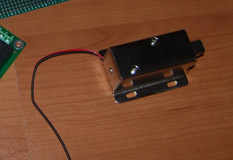
- Bolt

Assembly of the circuit
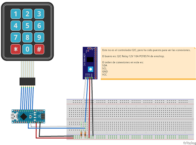
The Fritzing scheme is as follows:

As can be seen in the following images, the system has been mounted on a pcb board 9x15. The power supply has been chosen of 30A because each of the bolts uses 900 mA and there are 24 of these. The LM2596S module has been used to reduce the input voltage to the Arduino from 12V to 6V.
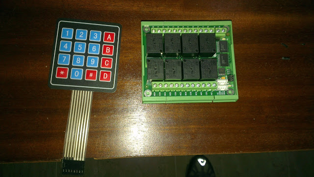
Images of the system mounted inside the laboratory:

Software
To verify the address I2C of the relay block has been used the program called Arduino I2c Scanner.
The libraries used have been:
- I2C_RL8xxM: library used to access the relay block.
- Wire: library used to I2C connections and is a dependenciy of the I2C_RL8xxM library.
- keypad: library used to manage the membrane keypad 4x3.
The code of the Arduino is the following:
#include <Wire.h>
#include <I2C_RL8xxM.h>
#include <Keypad.h>

/**
Filas y columnas del teclado
*/
const byte ROWS = 4;
const byte COLS = 3;

/**
@brief Asignación de pins de las patas
*/
byte rowPins[ROWS] = {9, 8, 7, 6};
byte colPins[COLS] = {5, 4, 3};

/**
@brief Define los simbolos de los botones del teclado
*/
char Keys[ROWS][COLS] =
{
  {'1', '2', '3'},
  {'4', '5', '6'},
  {'7', '8', '9'},
  {'*', '0', '#'}
};

/**
@brief Inicializa el teclado
*/
Keypad keypad = Keypad(makeKeymap(Keys), rowPins, colPins, ROWS, COLS);

char key;

//Tiempo restante de botones
int botones[8] = { 0, 0, 0, 0, 0, 0, 0, 0};

int estadoBotones[8] = {0, 0, 0, 0, 0, 0, 0, 0}; // 0 es desactivado y 1 es activado.

int segundosEspera = 60;

//Se declara una variable que almacenará el tiempo actual (real) transcurrido
//desde que se enciende la placa.
unsigned long tiempo = 0;

//Se declara una variable que almacenará el último valor de tiempo en el que se
//ejecutó la instrucción (delay).
unsigned long t_actualizado = 0;

//Se declara una variable que almacenará el tiempo que se desea que dure el delay.
unsigned long t_delay = 1000; // Por ser milisegundos, nos esperamos un segundo.


int DirReles = 32;

I2C_RL8xxM rb (DirReles);

int pinLed = 13;

void setup()
{
  Serial.begin(9600); //Para debug
  Serial.println("Inicio");

  Wire.begin(); //Inicializa el I2C como master
  keypad.addEventListener(keypadEvent); // Añade un gestor de eventos para el teclado

  pinMode(13, OUTPUT);
}

void activaRele(int numRele)
{
  Serial.print("Rele activado: ");
  Serial.println(numRele);

  if (estadoBotones[numRele - 1] == 0)
  {
    estadoBotones[numRele - 1] = 1;
    botones[numRele - 1] = segundosEspera + 2;

    rb.Switch (numRele, true);
  }
  Serial.println("Rele activado: FIN");
}

void apagaRele(int numRele)
{
  Serial.print("Rele desactivado: ");
  Serial.println(numRele);

  if (estadoBotones[numRele - 1] == 1)
  {
    estadoBotones[numRele - 1] = 0;

    rb.Switch (numRele, false);
  }
  Serial.println("Rele desactivado: FIN");
}

/**
Gestión de la tecla pulsada
*/
void keypadEvent(KeypadEvent key)
{
  Serial.print("Tecla pulsada: ");
  Serial.println(key);

  switch (keypad.getState()) {
    case PRESSED: //pulsado + soltado
      Serial.println("PRESSED");
      digitalWrite(13, HIGH);
      if (key == '0')
      {
        activaRele(1);
        activaRele(2);
        activaRele(3);
        activaRele(4);
        activaRele(5);
        activaRele(6);
        activaRele(7);
        activaRele(8);
      } else if (key == '1')
      {
        activaRele(1);
      } else if (key == '2')
      {
        activaRele(2);
      } else if (key == '3')
      {
        activaRele(3);
      } else if (key == '4')
      {
        activaRele(4);
      } else if (key == '5')
      {
        activaRele(5);
      } else if (key == '6')
      {
        activaRele(6);
      } else if (key == '7')
      {
        activaRele(7);
      } else if (key == '8')
      {
        activaRele(8);
      } else if (key == '9')
      {

      } else if (key == '#')
      {

      } else if (key == '*')
      {
      }
      break;

    case RELEASED: //Soltado
      Serial.println("RELEASED");
      digitalWrite(13, LOW);
      break;

    case HOLD: //Mantenido el botón pulsado
      Serial.println("HOLD");
      break;
  }
}


void testReles()
{
  for (int i = 0; i < 8; i++)
  {
    if (botones[i] == 1)
    {
      apagaRele(i + 1);
    }
    if (botones[i] > 0)
    {
      botones[i]--;
    }
  }
  //Serial.println("Comprobación estado relés");
}

//Se quita, si no el SoftTimer no funciona. Este lo tiene definido dentro.
void  loop()
{
  key = keypad.getKey();
  /*
    if (key) {
      Serial.print("Tecla pulsada: ");
      Serial.println(key);
    }*/

  //Se almacena el tiempo que ha transcurrido desde que se encendió el Arduino.
  tiempo = millis();

  //Si ese tiempo es mayor que el intervalo de deseado (equivalente al tiempo
  //de delay) se actualiza el intervalo y se ejecutan las instruciones relacionadas.
  //La idea detrás de este algoritmo consiste en pensar que si han transcurrido
  //20ms y se desea un delay de 30ms cada vez, cuando se superen esos 30ms la
  //variable con la que se compara pasa a ser 60ms. Una vez se alcanzan los 60ms
  //pasa a ser 90ms y así sucesivamente.
  if ( tiempo > t_actualizado + t_delay)
  {
    //Se actualiza el tiempo que ha de transcurrir para el próximo delay.
    t_actualizado = tiempo;

    testReles();
  }

}